

- Aviation
- 20 kL Cryogenic Liquid Medical Oxygen Vertical Storage Tank
- 10 kL Cryogenic Liquid Medical Oxygen Vertical Storage Tank Rafi Ahmad Kidwai Memorial District Hospital Barabanki UP
- 10 kL Cryogenic Liquid Medical Oxygen Vertical Storage Tank at MMG Hospital, Grand Trunk Rd, nr. Ghanta Ghar, Bihari Pura, Sarai Nagar, Naya Ganj, Ghaziabad, Uttar Pradesh 201001
- 10 kL Cryogenic Liquid Medical Oxygen Vertical Storage Tank at District Hospital Rampur UP Rajdwara Near State Bank of India 244901
- 10 kL Cryogenic Liquid Medical Oxygen Vertical Storage Tank at District Combined Hospital, Near Nahar Patri, village Mundet, Shamli UP 247776
- 10 kL Cryogenic Liquid Medical Oxygen Vertical Storage Tank at District Combined Hospital Hathras U.P.
- 10 kL Cryogenic Liquid Medical Oxygen Vertical Storage Tank at Combined District Hospital Mau U.P.
- 10 kL Cryogenic Liquid Medical Oxygen Vertical Storage Tank at Dr Ram Manohar Lohia Male Hospital Farrukhabad UP
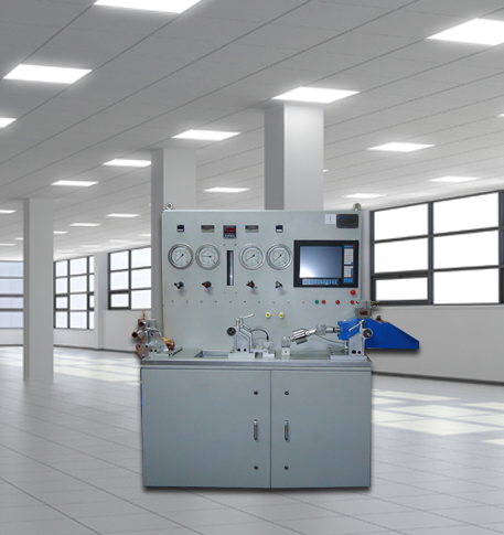
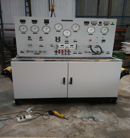
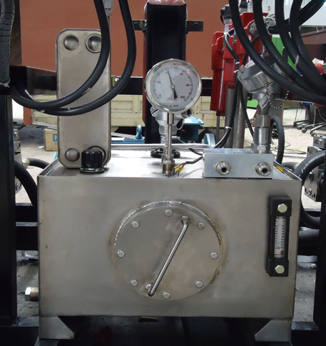
- 1000 Bar Hydraulic Proof Pressure Test Bench
- 20 kL Cryogenic Liquid Medical Oxygen Vertical Storage Tank
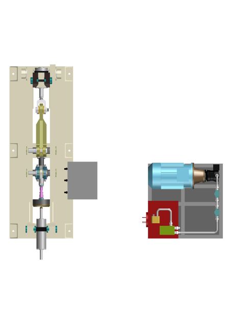
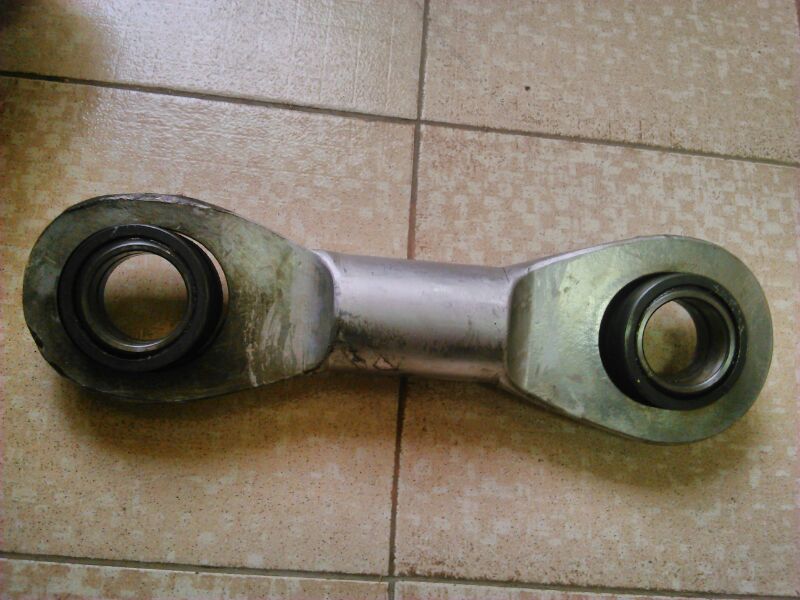
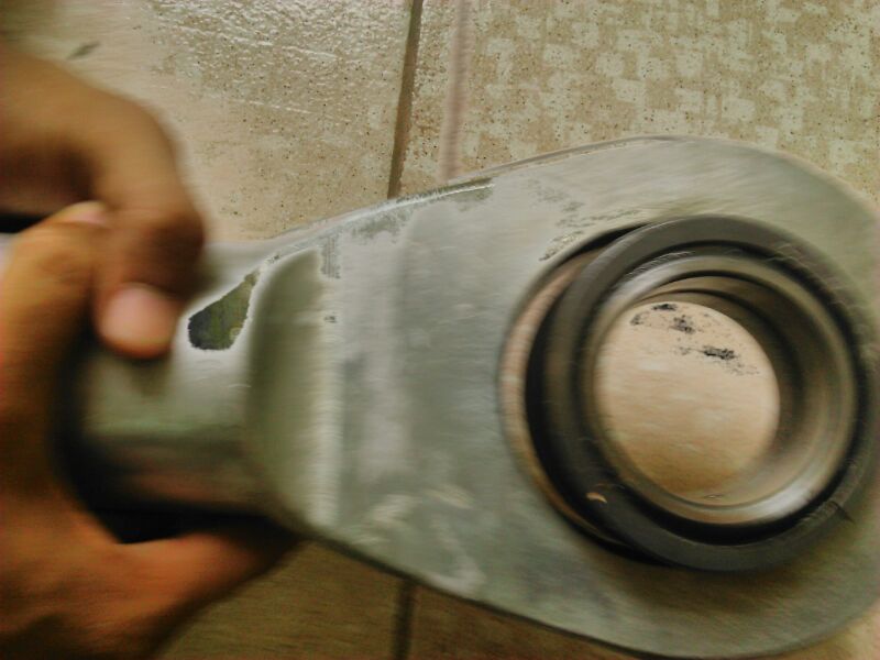
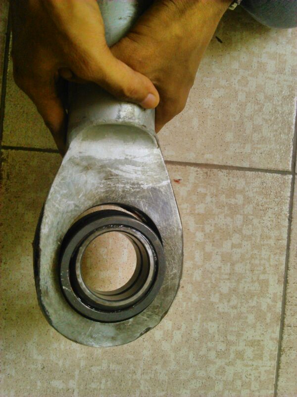
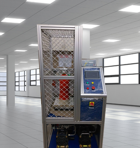
- 45 Degree Left And Right Moment Durability Test Rig
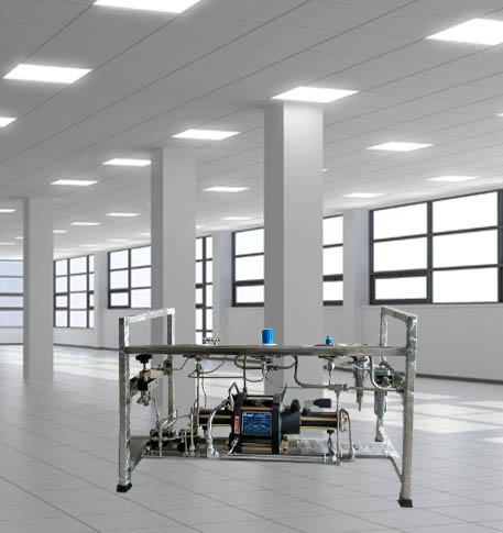
- ACM-test-bench
- Advance Valve Pressurepac-900 Bar
- Aero Engine Preservation
- Aircraft Arrester Barrier system Suratgarh
- Aircraft Arrester Barrier system Jamnagar
- Argon Heating and Cooling System
- Automated Inverter Test Rig On Labview Environment
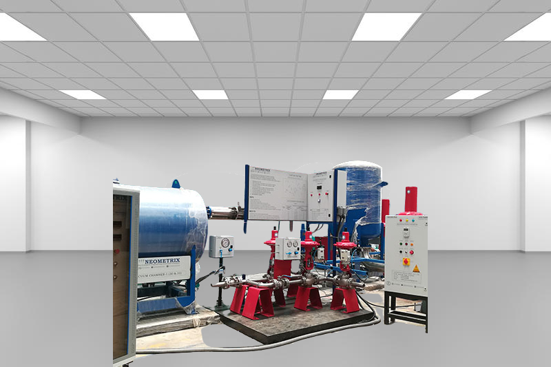
- Automatic Volumetric Expansion Test System
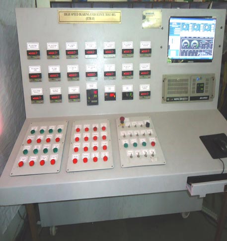
- 70000 RPM Bearing Test Rig
- BMP Pump Test Rig
- Bomb Shell Hydraulic Pressure Testing Machine Upto 1800-Bar
- Capacitor Inspection System
- CCB Burn Test Rig
- Chemical Cleaning Bay
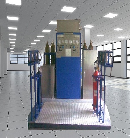
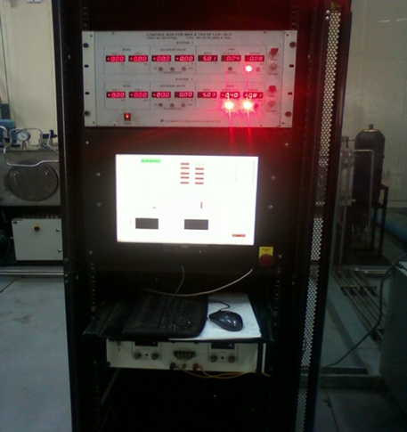
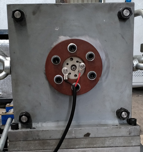
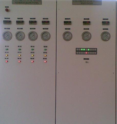
- CNG Circuit Leak Tester
- CNG Circuit Leak Testing Machine for Volvo Buses
- CNG High Pressure Regulator Test Bench
- CNG Regulator Test Bench
- CNG Vigilant
- CO2 & N2 Filling System
- cold air unit test bench
- Combined Control Unit Test Bench
- computerized control universal brake test bench
- Daq Sytem For Filter
- Distributor Valve Test Rig
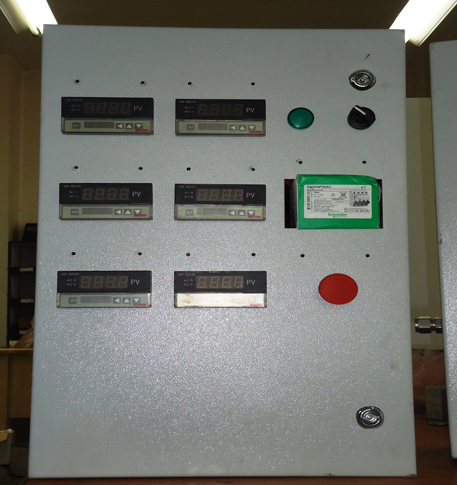
- DOPPLER VOR TEST RACK
- Dual Hydraulic Test System
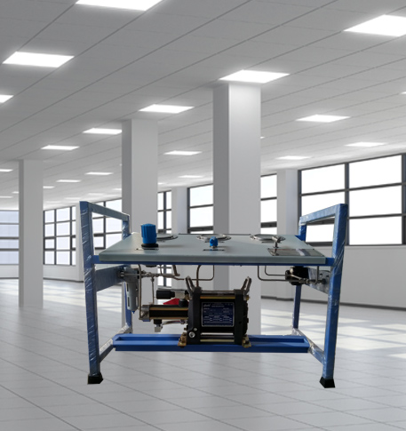
- ECS-test-bench
- Fuel Consumption Measurement System
- Fuel Injection Pump Test Bench
- Fuel Pump Test Rig
- Fuel (ATF) Pump Test Stand
- Gas Cabinets
- Gas Distribution System
- Gas Purging System
- Greenfuel-CNG Gas Flow Meter
- HAL BLR - Universal Hydraulic Test Rig
- Halon Reclaimation And Refiling Facility
- Head Impact Test Rig
- Helium Charging Station
- High Pressure Test Rig
- Hose Test Bench
- Hydraulic Control Valve Test Bench
- Hydraulic Damper Test Bench
- Hydraulic Direction Unit Test Bench
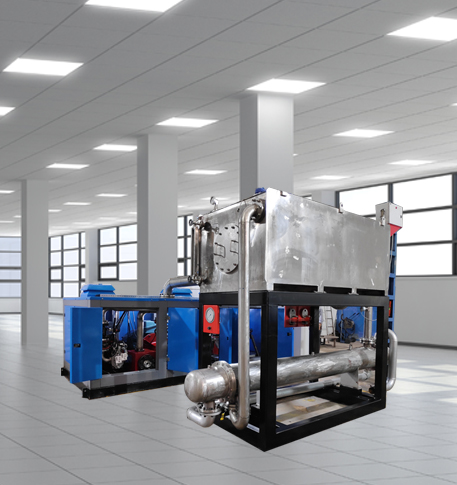
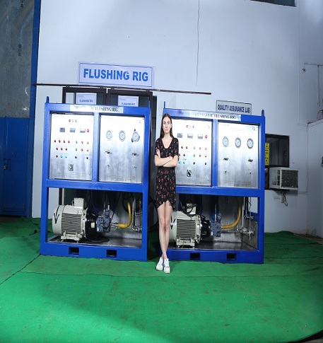
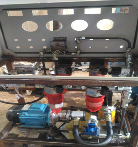
- Hydraulic Flushing Rig
- Hydraulic Powerpack and Actuator System
- Hydraulic Pressure Test Bench
- Universal Hydraulic Service Trolley HST-300U
- Hydraulic Snubber Test Bench
- Hydraulic Suspension Unit Test Bench
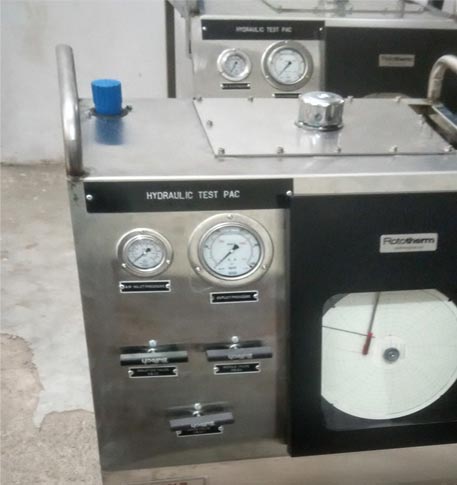
- Hydraulic Test Pac With Chart Recorder
- Hydraulic Test Rig Hs-748
- Hydraulic Test Rig Of Rear Cover Sub Assembly
- Hydraulic Manifold
- Hydrogen Gas Boosting Station
- Hydrostatic Test Bench
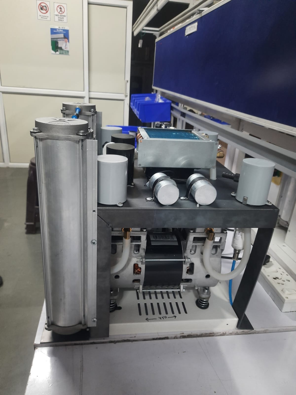
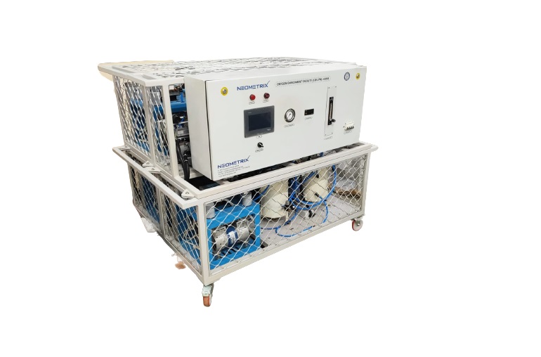
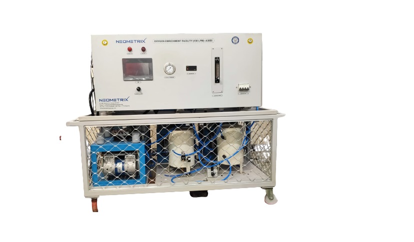
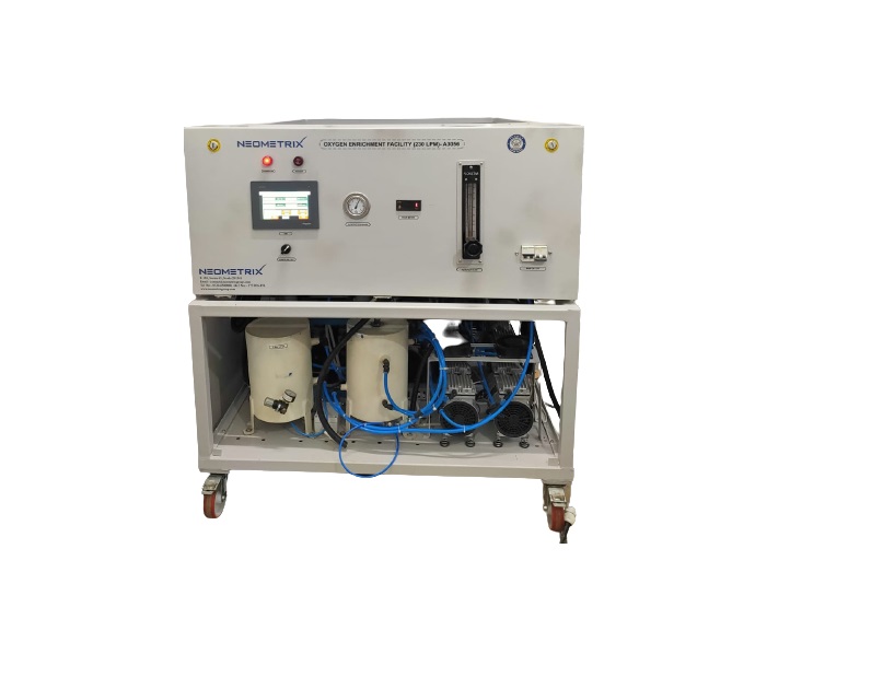
- Hypoxic Gas Generators
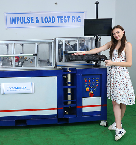
- Impulse & Load Test Rig
- Impulse Testing Machine For Hydraulic Hoses
- Inertia Test Facility
- KU-7 Oxygen Tester
- Loading Rig
- Main Rotor Actuator Test Rig
- Measuring Wheel Project
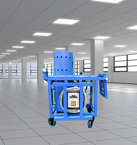
- Nitrogen cart with Booster
- Nitrogen Gas Boosting Station
- Nitrogen Purging System
- Oxygen Boosting System for Oxygen Generation Plant-PSA
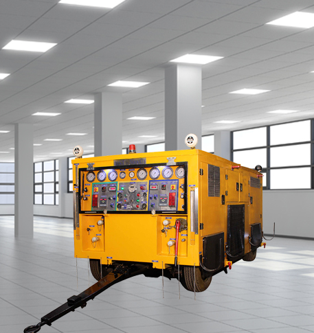
- Oxygen charging and distribution vehicle-UGSSO2
- Oxygen Gas Boosting Station
- PLC Controlled Autoclave Pressure Tester
- Pneumatic Test Rig
- Portable oxygen concentrator 10 LPM
- Portable Cylinder Nitrogen Trolley With Booster
- Power Shuttle Transmission Test Rig
- Pressure Cycle Test System
- Pressure Loss And Leak Test Rig
- Pressure Pac
- Pressurization of Test Tubes
- Priority Panels
- PSA-medical-oxygen-generation-plant-babu-eswar-sran-district-hospital-gonda-U.P.
- PSA medical oxygen generation plant CHC badi sadri chittorgarh rajasthan
- PSA Medical Oxygen Generation Plant Chc Chaurmastpur Ambala Haryana
- PSA Medical Oxygen Generation Plant CHC Dabi Bundi Rajasthan
- PSA Medical Oxygen Generation Plant CHC Dei Bundi Rajasthan
- PSA Medical Oxygen Generation Plant CHC Dungla Chittorgarh Rajsthan
- PSA Medical Oxygen Generation Plant CHC Hindoli Bundi Rajasthan
- PSA Medical Oxygen Generation Plant CHC Hospital Hati Kanpur Dehat
- PSA Medical Oxygen Generation Plant CHC Hospital Malsisar Rajasthan
- PSA Medical Oxygen Generation Plant CHC Hospital Mandalgarh Rajasthan
- PSA Medical Oxygen Generation Plant CHC Jaysinghpur District Sultanpur Uatter Pradesh
- PSA Medical Oxygen Generation Plant CHC Kapasan Chittorgarh Rajasthan
- PSA Medical Oxygen Generation Plant CHC Lambhua District Sultanpur Uatter Pradesh
- PSA Medical Oxygen Generation Plant CHC Sankoo Kargil Ladakh
- PSA Medical Oxygen Generation Plant CHC Saraswati Nagar Namunanagar
- PSA Medical Oxygen Generation Plant CHS District Hospital Kargil Ladakh
- PSA Medical Oxygen Generation Plant District Combined Hospital Kushinagar
- PSA Medical Oxygen Generation Plant District Combined Hospital Sanjay Nagar Ghaziabad
- PSA Medical Oxygen Generation Plant District Combined Hospital Shikohabad Firozabad
- PSA Medical Oxygen Generation Plant District Hospital Dakor Kheda Gujrat
- PSA Medical Oxygen Generation Plant District Hospital Katihar Bihar
- PSA Medical Oxygen Generation Plant District Hospital Maternity Wing Bijnor
- PSA Medical Oxygen Generation Plant District Hospital Maternity Wing Bulandshahr
- PSA Medical Oxygen Generation Plant District Male Hospital Hardoi
- PSA Medical Oxygen Generation Plant District Male Hospital Jalaun
- PSA Medical Oxygen Generation Plant District Women Hospital Bareilly
- PSA Medical Oxygen Generation Plant State Cancer Hospital Jaipur Rajasthan
- Oxygen Changeover Panel PSA To Manifold, For Gas Distribution
- PSA Medical Oxygen Generation Plant District Women Hospital Mainpuri
- PSA Medical Oxygen Generation Plant CHC Dei Bundi Rajasthan
- PSA Oxygen Generation Plant GMHC Bettiah Near Rama Maidhan West Champaran
- PSA Oxygen Generation Plant GMHC Bettiah Near Rama Maidhan West Champaran
- PSA Oxygen Generation Plant GMHC Bettiah Near Rama Maidhan West Champaran
- PSA Medical Oxygen Generation Plant Maharaja Suhel Dev Autonomous Medical College & Hospital Bahraich, U.P.
- PSA Oxygen Generation Plant Military Base Hospital Lucknow U.P.
- PSA Medical Oxygen Generation Plant Military Hospital Allahabad U.P.
- PSA Oxygen Generation Plant Military Hospital Danapur Patna
- PSA Medical Oxygen Generation Plant CHC Dabi Bundi Rajsthan
- PSA Medical Oxygen Generation Plant Sub District Hospital Dhamdaha, Purnia, Bihar
- PSA Oxygen Generation Plant CHC Saraswati Nagar Yamunanagar
- PSA Oxygen Generation Plant Railway Hospital Secundrabad (Nanded)
- PSA Oxygen Generation Plant Military Hospital Fatehgarh Farrukhabad
- PSA Oxygen Generation Plant Military Hospital Golconda Langar Houze Hyderabad
- PSA Medical Oxygen Generation Plant Sub District Hospital Dwarka Gujrat
- PSA Medical Oxygen Generation Plant Sub District Hospital Morbi Gujrat
- PSA Oxygen Generation Plant Sub Divisional Civil Hospital Jakhalabandha Asam
- PSA Oxygen Generation Plant Swahid Kushal Konwar Civil Hospital Golaghat Asam
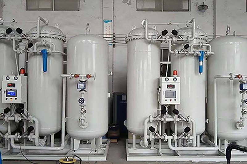
- PSA Medical Oxygen Generation Plants
- PSA Nitrogen Generation Plant
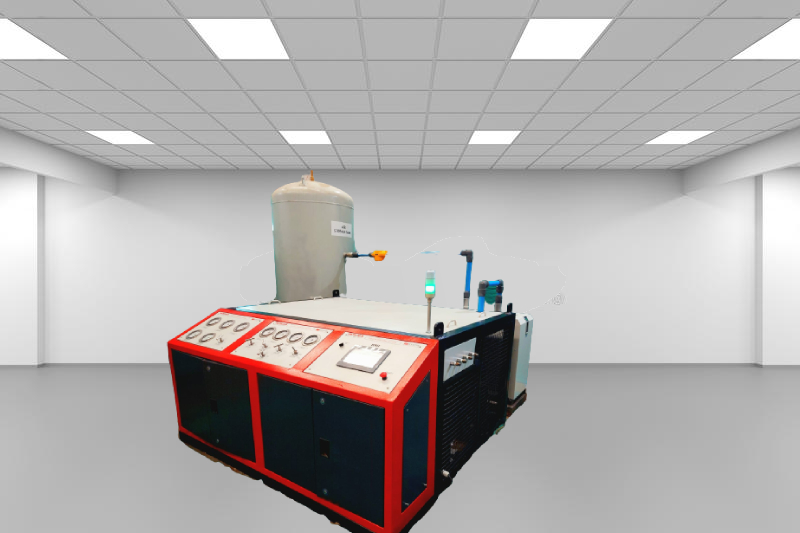
- Refrigeration System
- Refrigerator Door Endurance Testing System
- Rotor Dynamics Test Facility at AERDC
- Servo Hydraulic Actuators
- SF6 Recovery & Charging Trolleys
- CNG High Pressure Regulator Test Bench
- Starter Generator Test Rig
- Supply of Suction Lubrication System for 1000HP Cyclic Spin Test Facility
- Valve Test Rig
- Universal Hydraulic Test Rig
- Universal Hydraulic Service Trolley
- Universal-Hydraulic-Charging-Rig-Nasik
- Through Hole Inspection
- Test Rig For IRAB Brake System
- Test Pac
- Test Pac Digital
- TACAN Test Bench
- Test Rig For A9 Automatic Brake Valves
- Test Rig For SA9 Automatic Brake Valves
- Test Rig For C2W Relay Valves
- Test Rig For C2W Relay Valve 6mm Chock Valves
- Test Rig For MU-2B Valves
- Test Rig For F1 Selector Valves
- Test Rig For N1 Reducing Valves
- Test Rig For Feed Valve C2N-FT1 Combined Feed Valves
- Test Rig For C2W Distributor-brake-valves
- Test Rig For Duplex Check Brake Valves
- Test Rig For GM Type Drain Valves
- Test Rig For 24-A Double Check Valves
- Test Rig For R-6 Relay Valves
- Test Rig For Air Flow Measuring Valves
- Test Rig For J-1 Safety Valves
- Test Rig For Emergency Brake Application Valves
- Test Rig For Pressure Switch Valves
- Test Rig For Magnet Valves
- Computerized Based Test Bench For Panel Mounted Brake System For LHB Coches
- Distributor Valve Test Rig
- DV Test Rig
- Hydraulic Power Pack 230lpm/210 Bar
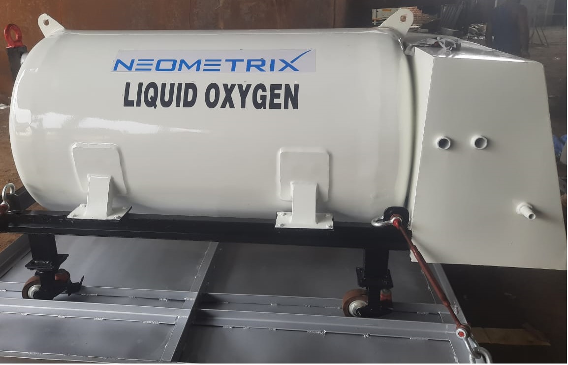
- Liquid Oxygen Dispenser 800 Ltr along With Towable Trolley
- CCTV Surveillance System Including Sensor For Infrastructure Protection
- Hydraulic Flushing Rig Nigeria
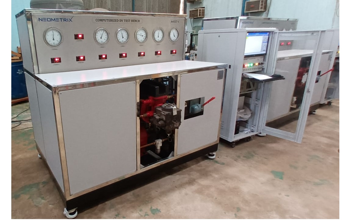
- Computerized Microprocessor Controlled Dv Test Bench
- CM Transportation Modules
- Universal Hydraulic Test Bench Aircrafts
- Hydraulic Refilling Trolley
- Drive And Control Automation System
- Modern Universal Automatic Test Equipment
- PSA Medical Oxygen Generation Plant 2400 LPM Jammu Kashmir
- 10 kL Cryogenic Liquid Medical Oxygen Vertical Storage Tank AIIMS Rishikesh Uttarakhand
- Mobile Test Facility for Aircraft Engines
- PCB Functional Test Bench
- Optical Test Bench For PCB And Optic Testing
- PCB Thermal Test Bench
- Ground Power Unit (GPU)
- Starter Generator Test Bench for Advanced Light Helicopter
- Lock Loading Test Rig
- Test Rig for 130LPM Pump of LCA
- Hydraulic Hose Leak Test Rig
- Hydraulic Loading System
- Dynamometer Engine Test Rig
- Digital Barometer
- Test Rig For Hydraulic Fluid
- Neometrix Optical Balloon Theodolite
- E-148 Sector-63,
Noida, Delhi-NCR, UP, India -
Sales & Service - +91 7777-876-876
+91 (0120) 4500-800 (100 Lines)
